THE ANATOMY OF A SIGNAL: Key information revealed at the speed of light
In part I we’ve recognized that signal travels in sensor metal (steel or aluminum) at the speed of sound.
This is true always for load cells where signals exit sensor directly to readout indicators. However for rotating applications where signal has another gap to jump from a strain gauged rotating shaft to a stagnant housing, another element is introduced with its very own technology.
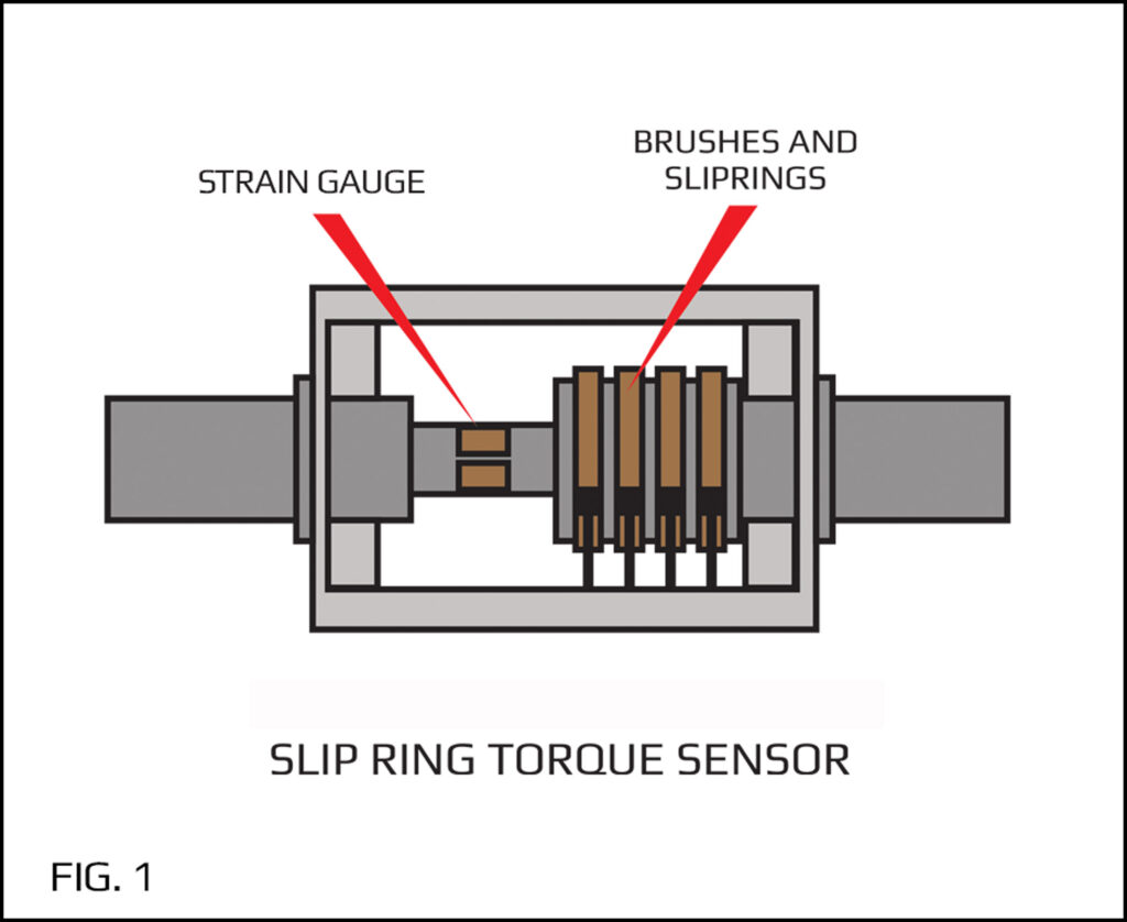
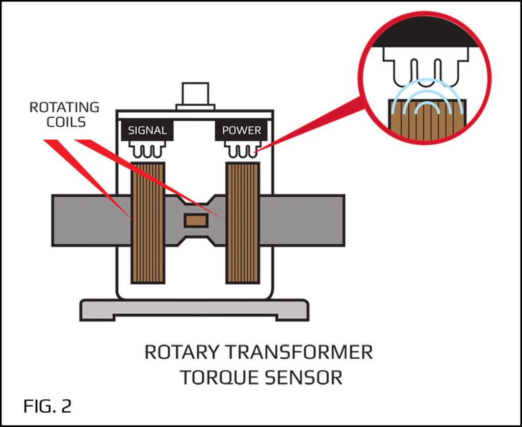
Shown below are two of the most common torque sensors used; slip ring (FIG 1) and rotary transformer (FIG 2).
THE ANATOMY OF A SIGNAL: Key information revealed at the speed of light
The slip ring torque will more or less convey the signal the same way a load cell does. However the rotary transformer will communicate with its stationary housing through magnetic fields created by high frequency AC currents run through specially designed coils. Design specifics are not discussed here; it is the speed of signal jumping from the rotating shaft to the stagnant housing rather that is of interest here.
The speed of any electromagnetic waves in free space is the speed of light
c = 3 E8 m/s
Hence for all practical considerations, signals travel through sensors (load cells, torque sensors) at least at sound speed which makes these sensors capable of accurately measuring any event of time “T” more than 1.806E-5 sec (55,357 Hz).
It is the recording / storing of signals into data acquisition instrumentation that signal frequency becomes a decisive factor. This will be discussed in parts III and IV.
Once again, for all practical purposes, if the electrical energy induced in rotating shaft needs to cross the gap to a stationary housing, it does that at the speed of light.
Surprisingly, things start slowing down when computers introduce themselves as modern means of better presentation and/or storing of mass data.
Our popular i100 hand held simulator generates precise mV/V signals to help develop, “troubleshoot,” and calibrate strain gage signal conditioners, instruments, signal processors, and data loggers.
Accuracy is ± 0.03%, temperature effects are 6 ppm/F, and zero balance is 0.0004 mV/V. Resistance of the i100 simulator is equivalent to a 350-ohm bridge. The i100 has 8 switch selectable output steps. Also, a Vernier knob is provided to allow the user to continuously adjust the output from –2 to + 2 mV/V. A convenient switch provides true reverse polarity. Connection to the i100 is made through either a PT style connector or 4 color-coded spring-loaded test clips. All critical internal contacts are gold plated. The i100 is compatible with AC carrier or DC strain gage signal conditioner electronics.
We love helping our clients excel. We are happy to discuss your sensor requirements and provide ideas on how you can become more competitive, productive and profitable with SDT products.